Real Simulation LED loading
From: Author: Publish time:2012-02-20 21:13 Clicks:525
Real Simulation LED loading
1. Entering LED mode
Press the key Shift + R-set to enter LED mode menu.
|
LED Mode |
|
LED Mode Set *Enter LED Mode Return
|
Choose the item Enter LED Mode and enter LED mode.
2. Setting the parameters
Press the key Shift + R-set to enter LED mode menu. Then select the item LED mode set to set the parameters. The rotary knob at the upper right front panel can be used to adjust the Vo.
|
LED Mode Set |
|
*LED Vo : 12.000 V LED Io : 0.3500 A Rd Coeff: 0.173 Return |
LED Vo : LED power supply working voltage
LED Io : LED power supply working current
Rd Coefficient: Working point resistance coefficient(range 0.001 ~ 1)
3. Rd Coefficient significance
IO is working current, which should be set as the rated current of measured LED power supply.
Vo is working voltage, which can be set as any value of output voltage range of the measured LED power supply
Rd is LED power supply inherent parameter, which can be found in LED power supply specification. Please refer to the part 4 for the detail.
Rd Coefficient = Rd / (Vo / Io)
Note:Vo、Io、Rd Coefficient are all the parameters describing the LED characteristic. Since the actual output current of LED power supply slightly deviates from the rated current, so there is also a slight deviation to the actual output voltage. This is normal.
4. Counting Rd Coefficient
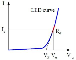
Suppose there is a LED string, 10 LEDs in series. The V-I characteristic curve of a single LED is as follows:
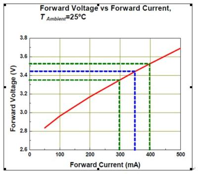
The output current Io of LED power supply is350mA. Then according to the above diagram, the working voltage Vo of a single LED is 3.44V.
The tangent line slope (ΔV/ΔI) of the working point is the operating point resistance Rd, so a single LED Rd = (3.52 – 3.35) / (0.4 – 0.3) = 1.7Ω
Coeff. = Rd / ( Vo / Io ) = 1.7 / ( 3.44 / 0.35 ) = 0.173
5. The advantage of setting Rd Coefficient
In LED power supply specification, there is voltage output range, for example: 9-36V. Different output voltage means different number of LED in series, and then Rd is different.
If setting Rd, each time when the test voltage is changed, Rd needs to be set again. It is very inconvenient. Since Rd is in proportion to the test voltage, users only need set an Rd Coeff and the electronic load will automatically count its corresponding Rd.
6. Simulating LED loading
After exit the menu, press the key On/Off and start loading. After LED power supply is connected to the electronic load terminals, then turn on the LED power supply because some LED power supply cannot be turned on with no load.
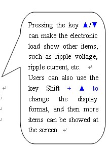
7. Observing average voltage/current and ripple voltage/current
|
LED ON |
|
Vpp = 0.29 V Vp+ = 25.23 V Vp- = 24.94 V |
|
Vo = 25.000V |
|
LED ON |
|
V = 25.088 V I = 0.35790 A P = 8.978 W |
|
Vo = 25.000V |
|
LED ON |
|
25.088V 0.35790A 8.978W 70.2556Ω 0.29Vp 0.0238Ap |
|
Vo = 25.000V |
|
LED ON |
|
Ipp = 0.0238 A Ip+ = 0.3690 A Ip- = 0.3452 A |
|
Vo = 25.000V |