
Load Effect Test
Load Effect Test
Load effect is a static performance test, providing the stable output for the measured power supply in programmed condition.
T63 series electronic load has load effect test function. In load effect test, users need to set the loading parameters, including the rated minimum current (Imin), the normal loading current (Inormal), the rated maximum current (Imax), and delay time(Delay). When starting the test, the electronic load will real-time display the electronic load regulation(regulation), the voltages (△ V) and the resistance of the power supply.
Vmax = Vdc @ Imin
Vnormal = Vdc @ Inormal
Vmin = Vdc @ Imax
△V = Vmax - Vmin
Regulation = (Vmax - Vmin) / Vnormal
Rs = (Vmax – Vmin) / (Imax - Imin)
In load effect test, the influence of connecting line is significant. In order to avoid such influence, it is recommended to use the remote sensing function of the electronic load to make the test.
Transient Response Test
Transient Response Test
The transient response test is a dynamic test, providing the stable output for the measured power supply periodically switching between two programmed load conditions.
In response to the current jump of the electronic load, the CV power supply will output ring voltage which causes the power supply feedback loop in disorder and forms voltage overshoot and voltage drop, thereby affecting the equipment operation reliability, and even damaging the voltage sensitive components. The transient response test can not only assess this performance from application aspect, but also reveal the critical defects causing the instability from the production aspect, such as the output capacitance’s ESR, ESL, capacity, the feedback loop response time, phase margin and the system maximum transient output current, etc.
1.2.1. Transient Response Process Analysis
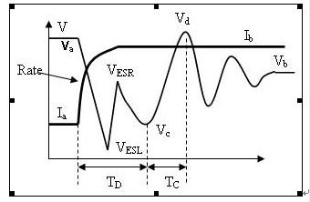
The principle of voltage overshoot is nearly the same with that of voltage drop. Here, we only discuss how current rise causes ring voltage, just as the above diagram shows:
(a) When the current rises according to the programmed current rising slew rate, due to the output circuit inductance and the influence of capacitance ESL, the output voltage, together with current rising waveform, will drop to VESL and forms the first wave trough of the voltage waveform.
(b) When the current becomes stable, due to the DC impedance of the output circuit and capacitance ESR, the voltage will recover to VESR and forms the first step.
RESR≈ (Va- VESR) /(Ib-Ia)
VESL ≈ Va –(LESL*Rate + (Ib-Ia)* RESR)
LESL ≈ (VESR -VESL) /Rate
(c) During this period, the power supply feedback loop is in disorder state. The loading current of the electronic load starts continuous discharge to the output capacitance(capacitance: COUT)until the feedback loop is established. Then the second valley value (VC) of the voltage waveform is formed. The discharge time (TD) is the feedback loop response time.
COUT ≈ TD*Ib / (Va - VC)
VC ≈ Va - Ib * TD / COUT
(d) When the voltage starts to rise from the second valley, the power supply starts charging to the output capacitance at the maximum current (ISYS) until the first peak valley Vd is formed. The charging duration is TC.
(VESR - VC) *TD/Ib ≈ (Vd - VC) *TC/( ISYS -Ib)
ISYS ≈ Ib * [(Vd - VC) / (VESR - VC) * TC/TD + 1]
(e) Thereafter, the voltage waveform will be in damping oscillation state. The smaller the oscillation cycle number n is, the greater the phase margin of the power supply loop is and the more superior the quality is.
1.2.2. Basic Requirement of Transient Response Test
a) Full range current rising time
According to the formula VESL ≈ Va –(LESL*Rate + (Ib-Ia)* RESR), the bigger the current change is and the higher the current rising rate is, the more obvious the change of the voltage overshoot and drop is and the more accurate the measurement is. In addition, the charge and discharge process of the output capacitance is interwoven with the response of the inductive reactance to current changes. In order to minimize the cross impact, it requires that the current transition time should be as short as possible, at least should be 5 times faster than that the feedback loop response time of the measured power supply. So transient response test has a very high requirement for the speed of the electronic load. The speed of the electronic load is generally expressed by the full range current rising time. The full range current rising time of the JT63 series electronic load is 10uS. Some people also use upper limit of the current rising time to describe the electronic load speed. Sine the upper limit of the current rising time=rated current/ full range current rising time, this index is not comparable among those equipments with different rated current.
b) Current slew rate programming
It is just because that the current changes has a big influence on the transient test, in order to make the measurement more objective, the test must be made at the same current rising slew rate. Thus, it is essential to have the function of current slew rate programming.
c) Electronic load D/A adjusting frequency
In respond to the current change, the inductive devices require the current to be steady and change continuously. While the current changes of the electronic load is realized through D/A digital processing, so D/A adjusting frequency directly determines the smooth degree of the current waveform and affects the measurement accuracy. The D/A adjusting frequency JT631 series electronic load is 500KHz.
d) Electronic load transient data measurement
JT63 series electronic load supports transient data analysis and measurement and real-display of the peak voltage (Vp+) and the valley voltage (Vp-). When the current rising slew rate is set very high or when ESL is very big and the influence quantity of ESL is more than that of the output capacitance charging and discharging, ESL will cause the first peak voltage, Vp+ and the first valley voltage(VESL),Vp-. Otherwise, if current rising slew rate is set very low or output capacitance very small, the influence quantity of the output capacitance charging and discharging is more than that of ESL, the output capacitance discharging will cause the second peak voltage Vp+ and second valley voltage (Vc) Vp-. If it is the first case, the Vp+ & Vp- measured value can directly show if there is some problems to the ESL and ESR of the output capacitance; if it is the latter case, Vp+ & Vp- measured value can directly show if there is some problems to the capacity value of the output capacitance. Users can also use the highest current slew rate to check the quality of the ESL and ESR first and then user a lower current slew rate to detect the capacitance capacity value and feedback loop response time.
e. Additional notes
Making the electronic load current as close as possible to the rated current of the power supply can significantly improve the measurement accuracy. Also note that sweep frequency in the transient test should not be too high so as to make the capacitance charging and discharging process reach steady state and improve the test accuracy. JT63 series electronic load provides dynamic frequency sweep function, which can help users capture the sweep frequency in the worst conditions, and meanwhile capture the peak voltage and valley voltage of this sweep frequency??. The transient response test, the connecting line not only exists impedance, but also has a bigger inductive reactance, and the influence is very significant. In order to avoid such influence, it is recommended to use the remote sensing function of the electronic load to make the test.
OCP Test
OCP Test
In order to protect the power supply, generally power supply has over current protection (OCP) function. Electronic load starts loading from the rated current of the measured power supply and gradually increases current value until the programmed current limit value. When the output voltage of the power supply drops to the load regulation, the output current at the moment is the current limit of the measured power supply.
JT 63 series electronic load has OCP test function. In OCP test, users need to set the starting current (Istart), ending current (Iend), steps (Steps), single step dwelling time (Dwell) and trigger voltage level (Vtrig). When starting the test, the electronic load will real-time display the output limit current (OCP), output maximum power (Pmax) and the voltage (V) & current (I) at the maximum power. If the measured equipment is solar battery, then this function can capture the maximum power.
Sometimes, you need to test the recovery conditions when in OCP state. Some power supplies can be recovered only when they are repowered on; some power supplies can be recovered only when the loading current is reduced to a very low value; some power supplies can be recovered only when the loading current is reduced to the rated current for a period of time. In certain conditions, the first two recovery conditions are not permitted, so it is necessary to test the recovery process when in OCP state by adjusting the electronic load current.
OVP Test
OVP Test
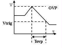
OVP test is used to test the protection voltage level and response time of the of OVP module of the power supply. JT63 series electronic load provides OVP test function. Users should set the trigger voltage level slightly higher than steady-state voltage level showed after OVP protection. Then simulate the power supply’s voltage rising process, the electronic load can capture and display the protection trigger voltage level and response time of the OVP module of the power supply. Users can adjust the adjustable potentiometer of the measured power supply or disconnect the feedback loop of the power supply or other ways to force the voltage of the measured power supply to rise higher than OVP voltage level protection value.
Start testing in the pre-load conditions, the detection power can normally start, as well as voltage and current destructive overshoot process
Start-up test
Start-up Test
Start-up test is used to detect if the power supply can be initiated normally and if there is destructive voltage overshoot and current overshoot in programmed loading condition.
The electronic load has four basic working modes: CC, CV, CP and CR. Besides, JT63 series electronic load also have the function of real-time displaying the peak voltage (Vp+) to detect if the output voltage of the power supply is overshoot. Moreover, users can also use an oscilloscope and current probe to observe the input current waveform of power supply and observe whether the surge current can cause some destructive effect.
If the measured power supply is CV source, you can use any one of the three modes of CC, CP and CR to make the test. But the principles of the three modes are different. In CR mode, the load will gradually increase the loading current according to the rise of power supply output voltage. Therefore, it has the least impact on the measured power supply. In CC mode, since the electronic load current feedback loop is in the disorder state when the power supply is turned off, the electronic load will starting loading at the maximum current at the moment the power supply is turned on. The duration of this process determines the speed of the feedback loop of the electronic load, so the faster the full range current rising time of electronic load is, the shorter the loading time, caused by the disorder of the feedback loop, is, and the smaller the negative impact on the power supply is. For the same electronic load, loading in CC mode has a stricter requirement to the start-up test than loading in CV mode. In CP mode, the electronic load not only starts loading at the maximum current at the moment the power supply is turned on, but also reduces the loading current to the steady-state value slowly according to the rise of the power supply output voltage. Therefore, loading in CP mode has the strictest requirement to the start-up test. It is recommended that users carefully select the working modes in start-up test according to the characteristics of their power supplies.
In addition, JT63 series electronic load also has Von / Voff function. Once enable Von/Voff function, the electronic load starts loading when the voltage of the power supply rise to the Von set value. Meanwhile, in CC, CP mode, the feedback loop will not be in disorder at the moment of turning on the power supply, thus, the loading transient process at the maximum current will be eliminated.
Note: there might be a big difference between cold start-up and warm start-up in the start-up test of the power supply. Thus, users should make several start-up tests after the power supply is turning off for a different period of time. At least ensure that the start-up test has been made once when the residual charge of the capacitance of the power supply is completely released.
PARD Test
PARD Test
Under other parameters in constant conditions, PARD is the periodic and random deviation of DC output voltage from the average within a specified bandwidth. PARD can be measured by RMS (root-mean-square) value or peak to peak value. Generally the bandwidth is from 20Hz to 20MHz. As to adopt RMS value or peak to peak value, it depends on the use situation. Peak to peak value can provide amplitude and peak information in short duration. While the RMS value is useful in determining the expected signal to noise ratio.
JT63 series electronic load provides real-time display of Vpp and Ipp, which is the PARD measured by peak to peak value. Since this PARD bandwidth is also restricted by the sampling frequency (500KHz), this PARD is a little different from PARD in general. If you need to detect the PARD with higher frequency of the measured power supply, you need to use an oscilloscope with higher bandwidth for help. If you need to detect PARD RMS value, you must use a true RMS voltmeter with high bandwidth.
Power Supply Startup Time / Hold Time Measurement
Power Supply Start-up Time and Hold Time Measurement
JT63 series electronic load has timing measurement function, which can achieve the power supply start-up time and hold time measurement. The trigger can be made either by the voltage level trigger of the current/ voltage rising/falling edge or by the TRI external trigger. The electronic load can count out the time interval of two signals occurring. When the starting trigger signal is made by the TRI external trigger and the ending trigger signal is made by the voltage level trigger of the voltage rising edge, if TRI signal can synchronize the opening of the input AC signal of the power supply, the measurement made at this time is the start-up time of the power supply. When the starting trigger signal is made by the TRI external trigger and the ending trigger signal is made by the voltage level trigger of the voltage falling edge, if TRI signal can synchronize the closing of the input AC signal of the power supply, the measurement made at this time is the hold-up time of the power supply.
Some power supplies have a high requirement to the response time of the power supply programming. At this time, the response time of the power supply programming need to be tested.
JT63 series electronic load has timing measurement function which can test the response time of the power supply programming. The electronic load can make the trigger by triggering the voltage level of the voltage/current rising/falling edge and count out the time interval of two signals occurring. When the starting trigger signal and ending trigger signal are made both by triggering the voltage level of the voltage rising edge, it can measure the rising time of the power supply. When the starting trigger signal and ending trigger signal are made both by triggering the voltage level of the voltage falling edge, it can measure the falling time of the power supply.
Cross Impact Test of Multi Channels Output Power Supply
Multi-channel Output Power Supply Cross-impact Test
When the power supply is multi-channel power supply, the cross-impact test is needed to be made. The test method is the same as that of the single machine alone. But the additional requirement is that different electronic loads can be synchronized.
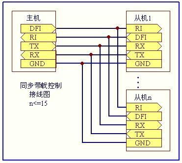
JT63 series electronic load supports up to 16 electronic loads synchronous master-slave control. This test can be made when users start the synchronous master-slave loading, and allocate different addresses to each of the slave loads, and disable the intelligent power allocation.
Automatic Test
Automatic test
JT63 series electronic load supports standard SCPI protocol, which can achieve the remote intelligent control and synchronization with other program-controlled measuring equipment and form a complete automatic test function. Besides, our JT 63 series electronic load is also equipped with standard isolated RS232 port.
JT63 series electronic load not only supports more test items and more intelligent extended mode, but also supports precision high speed digitizing measurement/ data capture(500kHz / 16 bits / 4096 points). With fewer equipments and faster speed, JT63 series electronic load can achieve overall automatic test function.
Automatic test alone
JT 63 series electronic load is functioned with the strongest automatic test of this industry. Users can program up to 8 files and each file is with 50 steps. The loading condition (Load), specification (SPEC) and delay time of each step can all be programmed. The delay time can be set as either waiting a trigger signal or any time ranging from 0.1S to 99S.
The user can also uses the trigger input function of the electronic load and access a foot switch between the TRIG signal and GND at the rear panel. The electronic load also provides the remote inhabit (RI) and device fault indication (DFI) signals, used for the information exchange, such as synchronization, with other program-controlled devices.